
Fuelcor Technology Summary
SYNTHETIC HYDROCARBON FUELS PLANT
WITH RECYCLING OF COMBUSTION PRODUCTS CO2 and H2O
USING CONVERSION OF NUCLEAR INTO COMBUSTION ENERGY
Fuelcor’s technology is in a process and system for producing hydrocarbon compounds or fuels that recycle products of hydrocarbon compound combustion – carbon dioxide or carbon monoxide, or both, and water. The energy for recycling is electricity derived from not fossil based fuels such as nuclear fuels or from renewable energy.
The process comprises electrolysing water, and then using hydrogen to reduce externally supplied carbon dioxide to carbon monoxide, then using so produced carbon monoxide together with any externally supplied carbon monoxide and hydrogen in Fischer-Tropsch reactors, with upstream upgrading to desired specification fuels – for example, gasoline, jet fuel, kerosene, diesel fuel, and others.
Energy released in some of these processes is used by other internal processes. Using adiabatic temperature changes and isothermal pressure changes for gas processing and separation, large amounts of required energy are internally recycled using electric and heat distribution lines. Phase conversion of working fluid is used in heat distribution lines for increased energy efficiency. The resulting use of electric energy is less than 1.4 times the amount of the high heating value of combustion of so produced hydrocarbon compounds when carbon dioxide is converted to carbon monoxide in the invention, and less than 0.84 when carbon monoxide is the source.
RECYCLING PROCESS
Complete combustion of hydrocarbon fuels like coal, natural gas, LPG, ethanol, methanol, gasoline, kerosene, diesel fuel, etc. results in two basic substances – carbon dioxide and water. When burning transportation fuels, the main reaction is as follows:
CnH2n+2 + (n+(2n+2)/2)*O2 → n*CO2 + (2n+2)/2 * H2O + Combustion energy (High Heating Value)
For average value of n=10, 10% more moles of water is produced than carbon dioxide. The number of oxygen moles used is equal to a sum of one mole for oxidizing carbon and a half of a mole plus 10% for oxidizing hydrogen, or 1.55 moles in total.
In a recycling process, we take the products of combustion and re-combine them into primarily transportation fuels, and also into some natural gas and LPG.
Transportation fuels are typically produced using Fischer-Tropsch process. In this process, carbon monoxide (CO) and hydrogen are ideally reacted as follows:
CO + 2H2 → (-CH2-) + H2O
(-CH2-) is a building block for “polymerization” into longer carbon chains using two available bonds shown by “-“ signs in parenthesis. The primary products of this polymerization are linear paraffins, CnH2n, plus two hydrogen atoms to complete any chain at the ends. It results in CnH2n+2 compound, the same as it was combusted.
In this reaction, one can conceptually envision one hydrogen molecule is used for formation of hydrocarbons, plus approximately 10% for completing chains at the ends, and another hydrogen molecule is used to reduce carbon monoxide to carbon.
There are a variety of processes to produce carbon monoxide from carbon dioxide, the product of combustion. We selected a chemical process called reverse water-gas shift reaction (RWGS). This reaction is as follows:
CO2 + H2 ↔ CO + H2O
In this reaction, one more hydrogen molecule is needed to reduce carbon dioxide to carbon monoxide.
In total, we need 1.1+1+1 = 3.1 hydrogen moles together with one carbon dioxide mole to produce hydrocarbon fuels in this way.
As the other product of combustion is water, we need, for pure recycling purposes, to produce this hydrogen from water as follows:
Externally supplied water 1.1 * H2O +
Water from RWGS reaction H2O +
Water from Fischer-Tropsch reaction H2O +
Electric energy for water electrolysis = 3.1* H2 + 3.1/2 * O2.
The amount of oxygen released is exactly the same amount as was consumed in combustion. All or part of water can be used from outside sources as well.
There are a variety of processes to produce hydrogen from water. We selected electrolysis of water.
BASIC OPERATION OF THE PLANT
The basic apparatus (plant) to produce transportation hydrocarbon fuels from the products of hydrocarbon fuel combustion is shown on Fig.1.
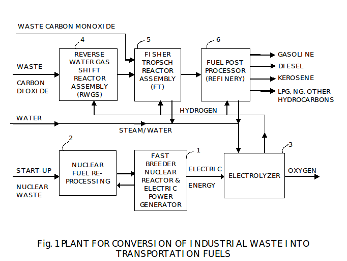
First, there is a source 1 of electric energy generated from heat of a nuclear reactor. It is preferred that this will be a fast breeder reactor. This reactor can be setup once with reprocessed nuclear waste, and then its nuclear core can be reprocessed at the re-processing plant 2 to extend the energy output from the world’s uranium reserves over 25 fold. At typical re-processing intervals of five years, there is plenty of initial fuel to power this apparatus until the end of its useful life, and way beyond.
The breeder reactors must be used in the long term to fully use reserves of the fissionable elements – uranium and thorium. The fast breeder is necessary only to fission highly radioactive actinides.
Any other type of a reactor can be used, especially Pebble Bed Modular Reactor (PBMR) that can be produced in volume at the factory and shipped for assembly on site. Use of thorium/uranium fuel mix will have advantages for this as well as any other type of reactor in view of much lower amount of nuclear waste.
Electric energy is used to electrolyze water to create hydrogen and oxygen in an Electrolyser 3. This water or a combination of steam and water is delivered from a) any external source and b) from other processes inside this apparatus.
We expect that most, if not all, of oxygen produced in the Electrolyser 3 will be put to uses elsewhere outside of this plant like in various furnaces for production of steel or in coal burners for electric power plants.
There are numerous uses in this apparatus for the hydrogen produced in the electrolyser. Hydrogen and carbon dioxide are used together in a reverse water gas shift (RWGS) reactor 4 to produce syngas, a mixture of carbon monoxide and hydrogen.
The preferred source of carbon dioxide is a plant emitting carbon dioxide as a byproduct, especially the plant that is required to reduce carbon dioxide emissions. The prime examples of such plants are various furnaces used in production of steel and fossil fuel electric power plants using coal. There are many other industrial sources of carbon dioxide as a byproduct, e.g. aluminum and cement plants.
As a byproduct of RWGS reactor operation, water is produced that is recycled back to the electrolyser.
The syngas (a mixture of carbon monoxide and Hydrogen) is fed from a RWGS reactor to a Fischer-Tropsch (FT) reactor 5. It is also possible to use waste carbon monoxide from existing industrial processes and combine this waste carbon monoxide with hydrogen instead of or in addition to syngas produced by the RWGS reactor 1-4. Examples of industrial processes emitting waste carbon monoxide are oxygen, ferroalloy, and carbide furnaces, acetylene and aluminum plants. It is preferred to use carbon monoxide instead of carbon dioxide as this materially eliminates the need for the RWGS process. This apparatus can also use a mixture or carbon dioxide and carbon monoxide as waste from industrial processes and complete carbon dioxide conversion into carbon monoxide in the reactor 4.
RWGS reaction is mildly endothermic and requires heat from external sources.
The main output of the FT reactor is a mixture of hydrocarbon compounds. Additional hydrogen is added to syngas or to carbon monoxide as required to adjust the desired output of the FT reactor. The byproduct is water that is recycled back to the electrolyser.
FT reaction is highly exothermic and produces heat that we use throughout this apparatus.
The main output of the FT reactor can be characterized as a version of crude oil. It is fed to post-processing (upgrading) plant 6 that is using existing refining processes. Some amount of hydrogen can be used in these refining processes. Such refinery is substantially simpler as its feed from the FT reactor is much closer in characteristics to fuels then crude oil.
The final outputs of this recycling plant are any desired transportation fuel, with future emphasis on high-octane de-sulfurized gasoline and de-sulfurized diesel fuel of a composition reducing the need for after-treatment in vehicles. One advantage of this apparatus is the flexibility of this apparatus to produce a variety of transportation fuels as a function of its modes of operation and not as a function of feed crude oil in existing refineries.
Now, we proceed with more details on each assembly of this plant.
ELECTRIC POWER GENERATOR
Electric power generator 1 is using heat generated by the nuclear power plant, preferably using fast breeder reactors. Any kind of nuclear power plant can be used in this apparatus. If a fast breeder type reactor is not used, then the plant would need periodic supply of nuclear fuel as commonly practiced.
It is also possible to use other sources of energy to generate electricity. Definitely, any hydroelectric or wind generators can be used as there is no waste heat required. The main criteria is production cost per kWh over the life of the plant.
ELECTROLYSER
There are numerous electrolysers to dissociate water or steam using electro-chemical reaction. At this time, water electrolysis is more developed than steam electrolysis. The basic construction is conventional and there are numerous commercial sources for such water electrolysers.
We favor use of bipolar electrodes for a high voltage and lower current stack of electrolytic cells and electrolyte consisting of water and potassium hydroxide.
From performance versus cost standpoint, it is either electrolyser design with high current density, for example 5-20 kA/m2, and catalyzed electrodes or with low current density like 1-3 kA/m2, and Raney nickel electrodes.
Modern electrolysers with high energy efficiency operate at operating temperature in 130 to 150 deg. C range and at operating pressure in 20-30 bar range, with 30% by weight of KOH in the electrolyte. Such operation leads to other internal energy efficiency of the overall fuel plant as other assemblies operate at similar pressure, and temperature difference is lower.
It is possible to achieve cell voltage around its thermoneutral (isothermal) level at some value of current in any construction. It means that if with supply of electric energy, this thermoneutral potential is reached, then no additional cooling or heating of cells would be required. If this potential will be lower, then additional heat will be required, and if higher – then cooling will be required.
If additional heat is required, it can be delivered via condensation of steam created by heat generated inside this apparatus.
We use multiphase electric rectifiers to reduce current pulsation in the electrolyser.
REVERSE WATER-GAS SHIFT (RWGS) REACTOR ASSEMBLY
The basic reaction is as follows:
CO2 + H2 ↔ CO + H2O
This reaction is widely encountered in the industry, for example in GTL plants and in Fischer-Tropsch reactors. This is a reversible reaction and its equilibrium coefficient to convert carbon dioxide to carbon monoxide is low. For this reason, we use excess of incoming gases, both carbon dioxide and hydrogen, to force complete conversion of the incoming carbon dioxide. The amount of hydrogen shall be enough for a) conversion to water inside the reactor and b) to form a near desired mixture H2/CO (syngas) to feed the FT reactor on the output. For example, for H2/CO ratio being around two (2), the amount of hydrogen moles shall be close to three times (3) the number of input carbon dioxide moles.
The amount of carbon dioxide at the input of the reactor shall be enough to achieve complete conversion of incoming carbon dioxide at a selected operating temperature of the reactor. In case of 400 deg. C operating temperature, it is preferred to use a 3-stage RWGS reactor with intermediate separation of steam. Then approximately 90-100% more carbon dioxide is required at the input of the reactor than incoming carbon dioxide. The additional carbon dioxide is coming from the feedback loop of this reactor assembly. This carbon dioxide is not consumed in the reactor and only circulates through it to change the equilibrium conditions for complete conversion of the incoming carbon dioxide.
Operating pressure in the reactors can be in the range of 4-30 bar, 20-25 bar is preferred. Steam is preferably separated at ambient temperature that leads to high separation ratio.
Each reactor needs heat as required by this reaction.
Any conventional catalyst for high temperature shift can be used, preferably with high selectivity to production of carbon dioxide. The example of a catalyst is KATALCO 71-5 produced by Johnson Matthey. Any type of catalyst bed can be used, fixed or fluidized.
This subassembly can process not only pure carbon dioxide but also a mixture of carbon dioxide and carbon monoxide. The mixture can be processed through one, two, or all three serially connected reactors, as a function of ratio of carbon monoxide to carbon dioxide.
FISCHER-TROPSCH (FT) REACTOR ASSEMBLY
The operation of a reactor is well known and described in a large number of publications. We present below a relevant summary of such operation for completeness of this presentation.
The basic reaction is as follows:
CO+2H2 → (-CH2-) + H2O
Dashes at (-CH2-) denote available bonds for either adding hydrogen or for polymerization. There are numerous hydrocarbon compounds produced in Fischer-Tropsch reactors as a function of the type of catalyst, operating temperature, pressure, and gas residence time in the reactor. For example, it operates with a cobalt catalyst at 220 deg. C and at 25 bar pressure and produces a mix of hydrocarbons leading primarily to production of a mixture of diesel fuel and gasoline. In other implementations of this process and at higher temperatures, like 350 deg. C, and with iron oxide catalyst, gasoline is almost exclusively produced. The amount of residual hydrocarbons that is difficult to convert into desired liquid fuels varies and generally is higher at higher temperature and lower at low temperature. Some of them are more valuable than fuels and are sold, and others are recycled.
The FT reactor produces both liquid hydrocarbons that are drained for further processing and gaseous hydrocarbons mixed with steam and input gases, carbon monoxide and hydrogen. For more complete conversion, several FT reactors can be used in series with removal of steam in between. It is also common to use the FT reactors operating at different temperatures and with different catalyst to create the desired mix of fuels, and to vary such mix.
On the output of the reactor, steam is separated from the effluent gas by a steam separator, then gaseous hydrocarbons with carbon numbers C5-C6 by another separator, and finally gaseous hydrocarbons with carbon numbers C3-C4 by one more separator. These separation processes can be combined as a function of composition of gas mixtures before separation. As a function of operating temperature, some hydrocarbon gases will be separated along with steam and then further separated from water. The residual gas contains mainly natural gas compounds methane CH4 and ethane C2H6, residual syngas gases CO and H2 and residual CO2. It is commonly practiced to return the majority of syngas to the input of the FT reactor via a recycle line, thereby improving conversion efficiency of incoming syngas into hydrocarbon fuels.
Instead of syngas, the FT reactor can be fed by an external to this apparatus source of waste carbon monoxide, and hydrogen from the electrolyser, or a mixture of these gases and syngas. Hydrogen is added on the input from the electrolyser to regulate the H2/CO ratio required by the FT reactors.
Vented gases (flair) in this apparatus are fed into a gas turbine-generator to produce electric power.
The reaction inside each reactor is highly exothermic. This reaction heat is removed, preferrably isothermally, using phase conversion of working fluid from liquid to gaseous phase.
POST PROCESSING (UPGRADING)
These are processes using existing technologies to convert hydrocarbon streams from the FT assembly into desired fuels, and other products if so desired. Typical upgraders include hydrocracking of FT waxes and reforming of naphtha. It is important to note that additional need in hydrogen is satisfied with hydrogen from the electrolyser. These processes are used in conventional refineries, but are simpler as the FT streams are much closer in compositions to desired fuels than crude oil.
ENERGY EFFICIENT GAS PROCESSING AND SEPARATION
Introduction
We presented a combination of known processes to recycle the products of combustion back into fuel using conversion of nuclear energy into electric energy and further into combustion energy in fuels. Economics of this process rests on energy efficiency of conversion of electric energy into combustion energy.
The described processes use large amounts of gas mixtures that must be heated and cooled, compressed and expanded, and condensed and evaporated in relevant gas separators. These processes use large amount of energy. Below, we present gas processing devices and methods leading to high level of recyclability of energy used for these purposes, and thereby achieving high energy efficiency of the overall plant.
METHODS AND DEVICES
There are two energy efficient thermodynamic processes that we use for gas processing. The first one is an adiabatic process when all external work is converted to or from gas energy. We use this process to change gas temperature, contrary to using heat to change temperature. The second one is an isothermal process, when all external work is either converted into heat or derived from heat. We use this process to change gas pressure, contrary to using compressors or expanders alone. On Fig. 2, we present a diagram of a universal gas separation using these two processes.
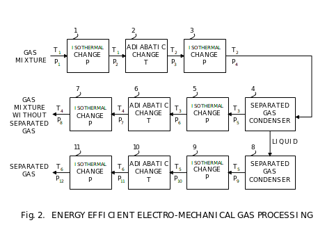
First three processes 1 through 3 condition a gas mixture for separation of one of its components by condensation in the condenser 4. Then next three processes 5 through 7 condition the residual gas mixture for further processing. The separated gas is in liquid phase in the condenser 4. If it is desired for further processing in a gaseous phase, then it is evaporated in the evaporator 8, and then is conditioned for further processing by processes 9 through 11.
Each group of processes, either 1 through 3, or 5 through 6, or 9 through 11, are identical in their principal functioning. They are centered on conditioning of gases for adiabatic processing to avoid any gas mixture component from changing phase, either to liquid or solid. Each process begins with adjusting pressure isothermally. Next, the gas or mixture of gasses is processed adiabatically to change temperature. After this process, the final isothermal process changes pressure as required for further processing. In summary, pressure is changed isothermally, and temperature adiabatically. This is a universal gas processing. In any specific place in the fuel plant, it might not be necessary to use all of the elements, but only some as required by conditions of temperature, pressure, and required separation if applicable.
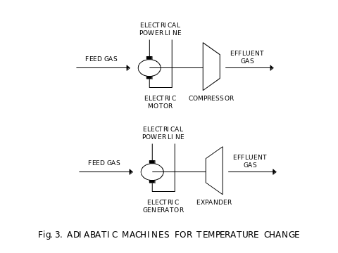
On Fig. 3, we show adiabatic machines for convenience, one to increase temperature and pressure by compression using power from an electric power line, and one to decrease temperature and pressure and generating power to an electric power line. We use an electric power line as both, a source and a recipient of power delivered or derived from adiabatic processes. The compressor is preferred to be a turbine driven by an electric motor, and the expander is also preferred to be a turbine driving an electric power generator. Such generator must be synchronized to the frequency of voltage in the electric power line and to match that voltage value and phase, very similar to other generators used in electric power grid.
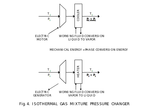
On Fig. 4, we show isothermal machines for convenience, one to increase pressure and one to decrease it. In the machine to increase pressure, we use a compressor driven by electric motor and the resulting gas mixture receiving power from the electric power line is both, compressed and heated. Heat is removed by a cooler. Amount of heat removed is equal theoretically to mechanical energy delivered using the electric power line. For large changes in pressure, several serially connected isothermal pressure changers can be used. In this case, they are called interleaved compressors. They are interleaved with coolers. The opposite process is for reducing pressure isothermally. In this case, the gas mixture is expanded and this reduces both, its pressure and temperature. Change in temperature is compensated by heating. Again, the amount of heat delivered to the mixture is equal theoretically to amount of mechanical energy fed into an electric power line by the electric generator driven by an expander. It is preferred to use turbines as both, compressors and expanders. In the interleaved construction, different gases or their different amounts can be condensed and separated at different stages.
We use coolers and heaters in the isothermal machines. These are heat exchangers. For isothermal operation, it is preferred to use phase conversion of a working fluid to deliver or remove heat to and from gases passing through these heat exchangers. This allows to process heat with near zero change in temperature.
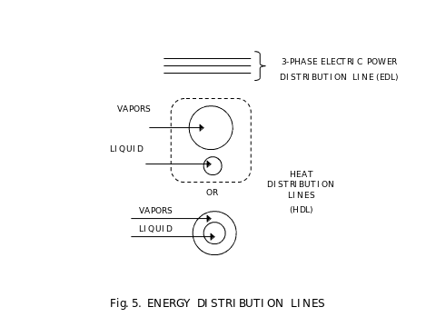
On Fig. 5, we show several energy distribution lines used in the described apparatus. First, it is an electric power line that delivers power to all uses – the electrolyser and all electric motors – and receives power from all sources – the electric power plant and all internal electric power generators. Others are heat distribution lines. They deliver heat or accept heat from various sources and uses of heat. Each line consists of two parts, the liquid part and the vapor part. When heat must be delivered from a line, then vapors are taken into a heat exchanger dedicated to accept this heat, condense in this heat exchanger and release heat, and condensed liquid is delivered in the other half of a heat distribution line. When heat must be accepted, the reverse process is used, liquid is evaporated into vapors.
In the apparatus described, we need the following temperatures at which phase conversions occur:
-
At a temperature of the RWGS reactors, typically 400 deg. C
-
At a temperature of the FT reactors, in 220-350 deg. C range
-
At a temperature of water in the electrolyser, 130-150 deg. C
-
At ambient temperature
-
At a temperature of carbon dioxide and/or certain hydrocarbon gases separation, typically -55 deg. C
The following are examples of working fluids for these lines:
-
Ethylene glycol for the RWGS-line
-
Water for the FT-line, or a substitute at higher temperature, like ethylene glycol
-
Water for the electrolyser line
-
Ammonia for the ambient line
-
Ethylene for carbon dioxide line.
From an energy efficiency standpoint, gas processing should not use heat energy due to inevitable losses to entropy. Out of the four thermodynamic types of energy – heat, mechanical, internal energy, and entropy – we use all but heat. We use mechanical energy in adiabatic processes to change the internal energy of gases, or vice versa. In turn, changes in internal energy lead to desired changes in temperature. In isothermal processes, we convert mechanical energy into entropy, or vice versa. In turn, changes of entropy lead to desired changes in pressure.
Mechanical energy is derived from conversion of electric energy, either by use of electric motors to take electric energy or by use of electric generators to deliver electric energy. Both, the motors and the generators, are connected to an electric power line that recycles energy from the generators to the motors with net entropic loss from heating of bearings, windings, and armature. This heat loss is small and determines the residual inefficiency of electric energy recycling.
Entropy change in isothermal processes is used to change phase of working fluids in the heat distribution lines using heat exchangers, either from liquid to gas or from gas to liquid. It results in recycling of entropy through these heat distribution lines. Entropy delivered to a heat distribution line from a heat exchanger used in isothermal compression is delivered to a heat exchanger used for isothermal expansion. We do not let entropy escape as is most common, but instead recycle it. The inefficiency of this entropy recycling is connected with entropy loss in heat exchangers due to temperature gradient on the exchange interface. This loss can be made small by selecting the size of the heat exchangers.
RECYCLING OF HEAT FROM THE FISCHER-TROPSCH ASSEMBLY
Amount of heat generated in this assembly is substantial in relation to combustion energy of fuels. We use this thermal energy beneficially within the plant to satisfy energy needs of other processes. This is a separate energy recycling process adding to the overall improvement of energy efficiency of the overall plant.
Exothermic heat of the reaction in Fischer-Tropsch reactors is the major source of energy as follows:
a) To provide heat to the RWGS reactors as that reaction is endothermic.
b) To provide heat to the electrolyser when it is operated below its thermoneutral voltage .
c) To provide heat for balancing heat losses in all heat distribution lines, like thermal conduction and thermal radiation.
d) To generate electricity compensating for most of power losses incurred in energy recycling of gas processing energies.
Heat to the RWGS reactors operating at higher temperature than the FT reactors is delivered using a heat pump.Heat to the electrolyser and to other heat distribution lines is delivered as a waste heat from an electric power generator using the FT reactors in a function of a boiler.
Residual heat from the FT reactors is used to generate electric power with waste heat discharge at near ambient temperature.
Energy EFFICIENCY SUMMARY
A summary of data in Table 1 illustrates the calculation of efficiency and electric energy usage as described herein.
TABLE 1
|
Summary Table of Energy Flow in kJ |
||||
|
Carbon oxide feed |
CO2 |
CO2 |
CO |
CO |
|
Efficiency boundary |
min |
max |
min |
max |
|
Energy for electrolysis |
853 |
753 |
578 |
510 |
|
Energy for RWGS reaction |
41 |
37 |
– |
– |
|
Energy from FT reaction |
(146) |
(176) |
(146) |
(176) |
|
Energy for processing |
200 |
150 |
133 |
100 |
|
TOTAL ELECTRIC ENERGY (TEE) |
948 |
764 |
565 |
434 |
|
High heating value (HHV) of hydrocarbon compounds |
670 |
680 |
670 |
680 |
|
Energy efficiency, % (HHV/TEE) |
71 |
89 |
119 |
157 |
|
Electric energy use per unit of high heating value (TEE HHV) |
1.4 |
1.1 |
0.84 |
0.64 |
|
Excess (Deficit) of TEE, % |
40 |
10 |
(16) |
(36) |
The calculations are shown for two species of carbon oxides. For each specie, all values, as explained in the following exemplary description and leading to minimum efficiency, are combined in one column, and all values leading to maximum efficiency – in another. Efficiency is defined as a ratio of the high heating value of combustion of hydrocarbon compounds (HHV) to the total electric energy supplied to the process and the plant from an external source (TEE). Electric energy use is defined as a reciprocal value of efficiency, as TEE over HHV.
In the last line of Table 1, an excess or deficit of electric energy is shown. For example, in a case of using carbon dioxide as an input and having minimum efficiency, 40% more electric energy will be required than the high heating value of combustion of hydrocarbon compounds produced. In a case of using carbon dioxide as an input and having maximum efficiency, only 10% more electric energy required.
In case of carbon monoxide as an input, it is evident that substantially less electric energy will be required, as carbon monoxide has certain combustion energy versus carbon dioxide having none. For this reason, in case of carbon monoxide as an input and having minimum efficiency, 16% less electric energy will be required than the high heating value of combustion of hydrocarbon compounds produced. In a case of using carbon monoxide as an input and having maximum efficiency, it is 36% less.
The following is a description of the entries of Table 1, wherein for simplicity, all energies are shown per one carbon dioxide mole converted into hydrocarbon compounds. Data presented are for illustration purposes and will vary as a function of specific designs implementing this recycling process. We used numerous publicly available sources of data from third parties.
Electric energy required for electrolysis of water is between 274 and 286 kJ per mole of hydrogen, as a function of temperature and under current density providing isothermal operation. In the preferred embodiment, it is estimated that this will be 275 kJ. 3.1 moles of hydrogen are required to recycle one mole of carbon dioxide, thus, 853 kJ of electricity will be required, which is for isothermal operation. For lower current densities, this amount of electric energy will be lower, for an example of up to 100 kJ lower. In such a case, this deficiency will be supplied from the other processes in this plant. Naturally, for higher current densities, there will be a need for more electric energy and additional heat must be removed. Some of this heat can be recycled into feeding an electrolyser electrically via electric power generation. Naturally, all heat can’t be recovered and total energy consumption will increase.
The RWGS reaction is moderately endothermic and requires 37-41 kJ per mole of converted carbon dioxide, as a function of operating conditions. This is another process that can use heat produced in this plant.
The Fischer-Tropsch reaction is highly exothermic and produces 146-176 kJ per carbon monoxide mole converted. This reaction is a major source of heat in this plant.
Other energy needs comes from energy dissipated in the processes that are difficult to recover like losses in bearings, electric motors, transformers, rectifiers, radiation and convection losses, and the like, and from the difference in enthalpy of feedstock and effluent products. We estimated that these losses are in the range of 150-200 kJ per mole of carbon dioxide as a function of specific operating conditions for various assemblies of this plant.
Output from the FT reactors is a mixture of hydrocarbon compounds with different combustion energies. For this estimate, the high heating value of combustion is used as water is used for recycling. In a mixture of compounds, this energy is on the order of approximately 670-680 kJ per one converted carbon dioxide mole.
Using all these values, the amount of input electric energy is calculated per amount of high heating value of combustion of produced hydrocarbon compounds using that electric energy in the process and the system hereby described. This range is between 1.4 and 1.1 when only carbon dioxide is used on the input. In turn, this means that the system needs between 10 to 40% more electric energy from an external source than is contained in high heating value of combustion energy of hydrocarbon compounds with end products carbon dioxide and water.
In this system, there is a much lower usage of electric energy when carbon monoxide is used from an external source, versus using carbon dioxide. In the case of carbon monoxide, the system will need one less mole of hydrogen, and no heat for the reverse water gas shift reactors. Then energy required for water electrolysis will be in the range of 275 kJ/mol times 2.1 moles equal 578 kJ. In addition, the amount of losses in gas processing will be reduced by approximately one-third due to elimination of the RWGS process and carbon dioxide separation process, resulting in 100 to 130 kJ. This results in that external electric energy needs are between 0.64 and 0.84 of high heating value of hydrocarbon compounds.
For a detailed description of the invention, please read Fuelcor’s patents.